- 您现在的位置:买卖IC网 > Sheet目录871 > OKY-T/3-D12P-C (Murata Power Solutions Inc)CONV DC/DC 15W 12VIN 3AOUT
�� �
�
�OKY-T/3,T/5-D12� Series�
�Adjustable� Output� 3� and� 5-Amp� DOSA-SMT� DC/DC� Converters�
�CAUTION� :� If� you� routinely� or� accidentally� exceed� these� Derating� guidelines,�
�the� converter� may� have� an� unplanned� Over� Temperature� shut� down.� Also,� these�
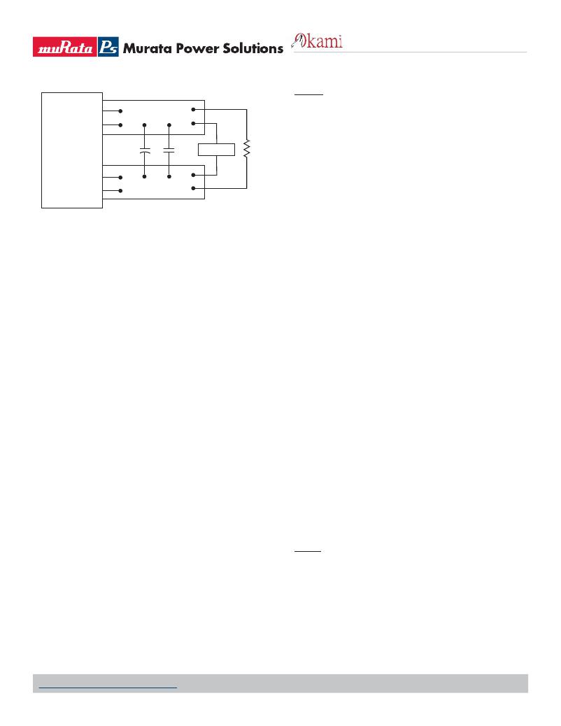
�+OUTPUT�
�COPPER� STRIP�
�graphs� are� all� collected� at� slightly� above� Sea� Level� altitude.� Be� sure� to� reduce�
�the� derating� for� higher� density� altitude.�
�Output� Fusing�
�C1�
�C2�
�SCOPE�
�R� LOAD�
�The� converter� is� extensively� protected� against� current,� voltage� and� temperature�
�extremes.� However� your� output� application� circuit� may� need� additional� protec-�
�-OUTPUT�
�COPPER� STRIP�
�C1� =� 1μF� CERAMIC�
�C2� =� 10μF� TANTALUM�
�LOAD� 2-3� INCHES� (51-76mm)� FROM� MODULE�
�Figure� 3.� Measuring� Output� Ripple� and� Noise� (PARD)�
�Minimum� Output� Loading� Requirements�
�All� models� regulate� within� speci?cation� and� are� stable� under� no� load� to� full�
�load� conditions.� Operation� under� no� load� might� however� slightly� increase�
�output� ripple� and� noise.�
�Thermal� Shutdown�
�To� prevent� many� over� temperature� problems� and� damage,� these� converters�
�include� thermal� shutdown� circuitry.� If� environmental� conditions� cause� the�
�temperature� of� the� DC/DC’s� to� rise� above� the� Operating� Temperature� Range�
�up� to� the� shutdown� temperature,� an� on-board� electronic� temperature� sensor�
�will� power� down� the� unit.� When� the� temperature� decreases� below� the� turn-on�
�threshold,� the� converter� will� automatically� restart.� There� is� a� small� amount� of�
�hysteresis� to� prevent� rapid� on/off� cycling.�
�CAUTION:� If� you� operate� too� close� to� the� thermal� limits,� the� converter� may�
�shut� down� suddenly� without� warning.� Be� sure� to� thoroughly� test� your� applica-�
�tion� to� avoid� unplanned� thermal� shutdown.�
�Temperature� Derating� Curves�
�The� graphs� in� this� data� sheet� illustrate� typical� operation� under� a� variety� of�
�conditions.� The� Derating� curves� show� the� maximum� continuous� ambient� air�
�temperature� and� decreasing� maximum� output� current� which� is� acceptable�
�under� increasing� forced� air?ow� measured� in� Linear� Feet� per� Minute� (“LFM”).�
�Note� that� these� are� AVERAGE� measurements.� The� converter� will� accept� brief�
�increases� in� current� or� reduced� air?ow� as� long� as� the� average� is� not� exceeded.�
�Note� that� the� temperatures� are� of� the� ambient� air?ow,� not� the� converter�
�itself� which� is� obviously� running� at� higher� temperature� than� the� outside� air.�
�Also� note� that� “natural� convection”� is� de?ned� as� very� ?ow� rates� which� are� not�
�using� fan-forced� air?ow.� Depending� on� the� application,� “natural� convection”� is�
�usually� about� 30-65� LFM� but� is� not� equal� to� still� air� (0� LFM).�
�Murata� Power� Solutions� makes� Characterization� measurements� in� a� closed�
�cycle� wind� tunnel� with� calibrated� air?ow.� We� use� both� thermocouples� and� an�
�infrared� camera� system� to� observe� thermal� performance.� As� a� practical� matter,�
�it� is� quite� dif?cult� to� insert� an� anemometer� to� precisely� measure� air?ow� in�
�most� applications.� Sometimes� it� is� possible� to� estimate� the� effective� air?ow� if�
�you� thoroughly� understand� the� enclosure� geometry,� entry/exit� ori?ce� areas� and�
�the� fan� ?owrate� speci?cations.�
�tion.� In� the� extremely� unlikely� event� of� output� circuit� failure,� excessive� voltage�
�could� be� applied� to� your� circuit.� Consider� using� an� appropriate� fuse� in� series�
�with� the� output.�
�Output� Current� Limiting�
�Current� limiting� inception� is� de?ned� as� the� point� at� which� full� power� falls� below�
�the� rated� tolerance.� See� the� Performance/Functional� Speci?cations.� Note� par-�
�ticularly� that� the� output� current� may� brie?y� rise� above� its� rated� value� in� normal�
�operation� as� long� as� the� average� output� power� is� not� exceeded.� This� enhances�
�reliability� and� continued� operation� of� your� application.� If� the� output� current� is�
�too� high,� the� converter� will� enter� the� short� circuit� condition.�
�Output� Short� Circuit� Condition�
�When� a� converter� is� in� current-limit� mode,� the� output� voltage� will� drop� as� the�
�output� current� demand� increases.� If� the� output� voltage� drops� too� low� (approxi-�
�mately� 98%� of� nominal� output� voltage� for� most� models),� the� magnetically�
�coupled� voltage� used� to� develop� primary� side� voltages� will� also� drop,� thereby�
�shutting� down� the� PWM� controller.� Following� a� time-out� period,� the� PWM� will�
�restart,� causing� the� output� voltage� to� begin� ramping� up� to� its� appropriate� value.�
�If� the� short-circuit� condition� persists,� another� shutdown� cycle� will� initiate.� This�
�rapid� on/off� cycling� is� called� “hiccup� mode”.� The� hiccup� cycling� reduces� the�
�average� output� current,� thereby� preventing� excessive� internal� temperatures�
�and/or� component� damage.� A� short� circuit� can� be� tolerated� inde?nitely.�
�The� “hiccup”� system� differs� from� older� latching� short� circuit� systems�
�because� you� do� not� have� to� power� down� the� converter� to� make� it� restart.� The�
�system� will� automatically� restore� operation� as� soon� as� the� short� circuit� condi-�
�tion� is� removed.�
�Remote� On/Off� Control�
�On� the� input� side,� a� remote� On/Off� Control� can� be� ordered� with� either� polarity.�
�Please� refer� to� the� Connection� Diagram� on� page� 1� for� On/Off� connections.�
�Positive-polarity� models� are� enabled� when� the� On/Off� pin� is� left� open� or� is�
�pulled� high� to� +Vin� with� respect� to� –Vin.� Positive-polarity� devices� are� disabled�
�when� the� On/Off� is� grounded� or� brought� to� within� a� low� voltage� (see� Speci?ca-�
�tions)� with� respect� to� –Vin.�
�Negative-polarity� devices� are� on� (enabled)� when� the� On/Off� is� left� open� or�
�brought� to� within� a� low� voltage� (see� Speci?cations)� with� respect� to� –Vin.� The�
�device� is� off� (disabled)� when� the� On/Off� is� pulled� high� (see� Speci?cations)� with�
�respect� to� –Vin.�
�Dynamic� control� of� the� On/Off� function� should� be� able� to� sink� appropriate�
�signal� current� when� brought� low� and� withstand� appropriate� voltage� when�
�brought� high.� Be� aware� too� that� there� is� a� ?nite� time� in� milliseconds� (see�
�Speci?cations)� between� the� time� of� On/Off� Control� activation� and� stable,�
�regulated� output.� This� time� will� vary� slightly� with� output� load� type� and� current�
�and� input� conditions.�
�www.murata-ps.com/support�
�MDC_OKY-T/3,T/5-D12� Series.B15� Page� 7� of� 21�
�发布紧急采购,3分钟左右您将得到回复。
相关PDF资料
OKY-T/3-W5N-C
CONV DC/DC 10.9W 5VIN 3AOUT SMD
OKY2-T/16-D12P-C
CONV DC/DC 80W 12VIN 16AOUT SMD
OKY2-T/16-W5P-C
CONV DC/DC 52.8W 5VIN 16AOUT SMD
OTBH156KNPIR-F
CAP FILM 15UF 1.5KVDC QC TERM
P-120AS/A22
BATT NICAD 4/5A 1200MAH S TYPE
P-120SCJS/A02T
BATT 1200MAH 4/5SC NICAD W/TAB
P-130SCS/A06T
BATTERY 1300MAH SC NICAD W/TAB
P-140AS/A16T
BATTERY NICAD A SIZE W/TAB
相关代理商/技术参数
OKY-T/3-W5N-C
功能描述:DC/DC转换器 5Vin 0.7525-3.63Vout 3A 10.9W NegPolarity
RoHS:否 制造商:Murata 产品: 输出功率: 输入电压范围:3.6 V to 5.5 V 输入电压(标称): 输出端数量:1 输出电压(通道 1):3.3 V 输出电流(通道 1):600 mA 输出电压(通道 2): 输出电流(通道 2): 安装风格:SMD/SMT 封装 / 箱体尺寸:
OKY-T/3-W5P-C
功能描述:DC/DC转换器 5Vin 0.7525-3.63Vout 3A 10.9W PosPolarity
RoHS:否 制造商:Murata 产品: 输出功率: 输入电压范围:3.6 V to 5.5 V 输入电压(标称): 输出端数量:1 输出电压(通道 1):3.3 V 输出电流(通道 1):600 mA 输出电压(通道 2): 输出电流(通道 2): 安装风格:SMD/SMT 封装 / 箱体尺寸:
OKY-T/5-D12N-C
功能描述:DC/DC转换器 12Vin 0.75-5.5Vout 5A 25.5W Neg logic
RoHS:否 制造商:Murata 产品: 输出功率: 输入电压范围:3.6 V to 5.5 V 输入电压(标称): 输出端数量:1 输出电压(通道 1):3.3 V 输出电流(通道 1):600 mA 输出电压(通道 2): 输出电流(通道 2): 安装风格:SMD/SMT 封装 / 箱体尺寸:
OKY-T/5-D12P-C
功能描述:DC/DC转换器 12Vin 0.75-5.5Vout 5A 25.5W Pos logic RoHS:否 制造商:Murata 产品: 输出功率: 输入电压范围:3.6 V to 5.5 V 输入电压(标称): 输出端数量:1 输出电压(通道 1):3.3 V 输出电流(通道 1):600 mA 输出电压(通道 2): 输出电流(通道 2): 安装风格:SMD/SMT 封装 / 箱体尺寸:
OKY-T/5-W5N-C
功能描述:DC/DC转换器 5Vin 0.7525-3.63Vout 5A 18W Neg Polarity
RoHS:否 制造商:Murata 产品: 输出功率: 输入电压范围:3.6 V to 5.5 V 输入电压(标称): 输出端数量:1 输出电压(通道 1):3.3 V 输出电流(通道 1):600 mA 输出电压(通道 2): 输出电流(通道 2): 安装风格:SMD/SMT 封装 / 箱体尺寸:
OKY-T/5-W5N-C
制造商:Murata Power Solutions 功能描述:DC/DC Converter
OKY-T/5-W5P-C
功能描述:DC/DC转换器 5Vin 0.7525-3.63Vout 5A 18W Pos Polarity
RoHS:否 制造商:Murata 产品: 输出功率: 输入电压范围:3.6 V to 5.5 V 输入电压(标称): 输出端数量:1 输出电压(通道 1):3.3 V 输出电流(通道 1):600 mA 输出电压(通道 2): 输出电流(通道 2): 安装风格:SMD/SMT 封装 / 箱体尺寸:
OKY-T10
制造商:MURATA-PS 制造商全称:Murata Power Solutions Inc. 功能描述:Programmable DOSA-SMT 10/16-Amp DC/DC Converters